Sketch Model Challenge: Trash Duck
The first project in MMAE 432, the Sketch Model Challenge introduces students to sketch modeling methods and materials, prototyping and craftsmanship, and is a fun and thought provoking project emphasizing strong teamwork and creativity.
Students will design and construct human propelled vehicles pushed or pulled by one student and capable of supporting another student as a rider. Students will be mindful of vehicle weight, and vehicles must be constructed of common sketch modeling materials such as foam or cardboard, and usage of other materials will incur severe weight penalties. Vehicles will be tested at the conclusion of the project in a friendly game of dodgeball.
Source: Profs. Matthew Spenko and Murat Vural
Over the course of 3 weeks, TheCreo team designed, modeled, tested, and constructed the Trash Duck, a 27lb Sketch Model sled carrying a rider and propelled by a pulling driver. Constructed from 2in pink insulation foam, cardboard tubes, laminating plastic, and canvas, the Trash Duck was developed through several design phases, from initial concept generation and analysis, to materials testing and CAD, to final construction. Equipped with a handheld shield and built-in rider protection, this defense-focused vehicle was surprisingly durable during both the dodgeball game and subsequent race, taking only minor cosmetic damage. Despite a distinct lack of snow, this sled was agile on the grass, and placed midfield in the race above other wheeled vehicles.
The project phases are outlined below:
4. Constructing the Trash Duck


Brainstorming 30 Vehicles
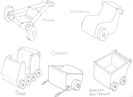
The final sled design, named the Trash Duck, was the product of the iterative concept generation and analysis process. Each group member presented 5 preliminary concepts. These 30 initial designs were classified into 4 chassis types to analyze the wide range of vehicle concepts. These 4 chassis types were frames, wheelbarrows, tanks, and chariots. Frame designs were characterized as lightweight, open, pushed designs designed around a cardboard shipping tube frame. Wheelbarrows were also pushed designs, characterized by a foam frame, single axle, and compact design. Tank designs were characterized by heavy rider protection or enclosure in the form or walls or built up bodywork, as well as an emphasis on durability over mobility with elements such as 6 or more wheels or treads. Chariot designs were pulled, and characterized by moderate rider protection and a focus on balancing mobility, durability, and size.
The benefits and drawbacks of these 4 vehicle types were analyzed in a Pugh Chart, where the datum was chosen as a 4 wheeled box vehicle. Factors considered were mass, rider coverage, durability of the design during the dodgeball game, and the rider’s ergonomics. Frame designs were predicted to be lightweight, but offered low protection or coverage for the rider. Wheelbarrow designs were not predicted to stand out in any particular area. Tank designs offered excellent rider coverage and durability at the cost of vehicle mass. Lightweight chariots were predicted to give durability due to a lowered hit probability owing to their compact design. Rider ergonomics were favorable on chariot designs because minimal rider enclosure allows easier movement.

Designing the Trash Duck
The final design combined aspects of both tanks and chariots. Frame designs were disqualified from the finalist designs both for their low score and for their prevalence in previous years because a more creative design was desired. Pulled vehicles were favored over pushed vehicles for greater directional stability and because heavily loaded tensile elements such as ropes or straps are more weight efficient than equivalently loaded compressive elements. The final chassis proposal had a durable tank-like chassis with allowance for multiple redundant wheels. The rider was protected by a partial bodywork structure with main protection coming from a handheld shield. As with a light chariot, this design was to be pulled by ropes or straps with the rider facing backwards with a clear line of sight to throw, uninterrupted by the driver.
From the first iteration of the hybrid tank-chariot concept, allowance for operation on snow or mud was made through the use of a smooth flat underside of the vehicle. One originally course of action called for the vehicle able remove or mount wheels to account for either soft or dry conditions. Crucially, however, the decision was made to design the vehicle as a sled only, without allowance for wheels. Although this appeared to be foolhardy, this decision was justified by several factors. With the upcoming polar vortex and deep freeze, snow was expected to be present. Even if the snow melted, slushy, muddy, and soft conditions were expected which would favor a sled over wheels. Because any special materials such as PVC or wood would incur a 30x weight penalty, using foam wheels was expected to bring a host of challenges, as well as adding on more weight to an already heavy design. Additionally, due the the tight time schedule for testing and construction, it was decided to take a more time-conservative approach of focusing on a wheel-less sled rather than devoting precious time to testing and developing a sturdy, reliable wheel. Although wheels seem to give much lower friction than a sled, friction testing with the laminating plastic on snow, as discussed below, gave very promising results. Based upon online research on the performance of pulled sleds such as pulks, ground pressure was determined to be an important metric in preventing the sled from sinking or sticking into snow or soft ground. As a functional requirement, 1 psi or less was determined to be appropriate, with less than 0.4 psi being optimal. The smooth underbody would be covered with the 5mil laminating plastic.
As the chassis design solidified, weight and durability refinements were applied to the rider enclosure. Originally a foam superstructure of 3 walls protecting the rider’s back and sides, this was found be heavy, adding around 6 pounds to the sled, while the foam was predicted to have questionable durability against dodgeball impacts due its stiffness, brittleness, and weakness at any joints. Instead, a canvas enclosure was designed. Held up by two cardboard tubes attached to a mounting on the chassis, the single layer canvas “tent” was predicted to be significantly lighter, weighing around 2-3 lbs only, while the soft fabric would hold up better to impacts due to its ability to deform and dissipate impact energy.
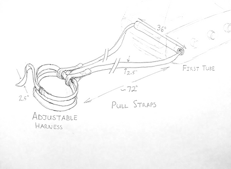
The last element of the sled design was the driver harness and pull straps. Because ropes were not permitted as a common material, canvas was chosen for these tensile elements.The canvas used in the project was 12oz (per sq yard) weight canvas for both the rider enclosure, harness, and pull straps. Both the pull straps and harness were derived from double layer, hand sewn canvas straps 2.5in wide. The pull strap passed through the first reinforcing tube of the chassis and was looped onto the harness straps. The harness was one long canvas strap wrapped twice around the driver’s waist, crossed in the rear with a double D-ring adjustable closure in the front. The cross strap design ensured that the tension would be distributed over the entire harness and that the pressure would be evenly distributed over the driver’s waist.

Materials Testing
Once chassis structure was determined, a set of experiments were conducted to determine relevant material properties in order to validate the structural stability of the proposed design.
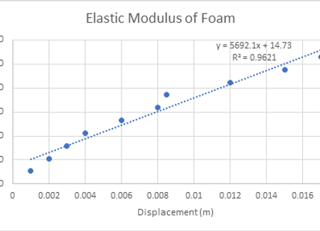
First, tests were conducted to determine the elastic moduli of the pink foam and of the cardboard tubes that would be used for the chassis. These values were then used in the subsequent FEA simulations. The experimental setup as shown was used to test elastic moduli.
The specimen was first measured for its cross sectional area and length. The specimen was clamped on one end of a table, to simulate fixed support for a cantilever beam. A scale was attached to the end of the specimen. The scale was pulled in increments of force. At each increment, the deflection of the beam was recorded along with the force supplied at that moment. Using the equation below, the values for Load were plotted against deflection in an excel plot and the elastic modulus was obtained from the slope of the linear regression line
Ed = PL/3I
Where P is the applied load, E is the elastic modulus, d is the measured beam deflection, L is the length of the test region of the specimen, and I being the second moment of area of the specimen’s cross section.
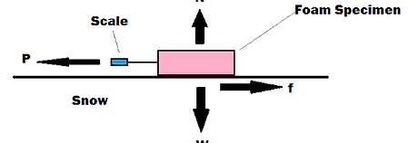
The coefficient of friction of the bottom surface of the chassis against expected terrain was also calculated to determine the expected loads the driver would need to apply to move the cart and if those loads were within acceptable limits to not fatigue the driver. Initially, testing was done to find the friction coefficient between the pink foam and grass and snow. The experimental setup used is shown below
Before testing, the specimen was weighed with a metal plate to add additional loading and the weight was measured to be 2.14kg. The specimen was pulled by the scale until it began to move. The force required to overcome static friction was recorded. This was repeated for ten trials and the average force to overcome static friction was calculated. Using a summation of forces in the x and y directions for static equilibrium, the following equations were derived.
P =f
N=W
Where P is force applied, N is the normal force, W is the weight of the specimen, and f is the friction force. Using the relationship between normal force and friction force in static equilibrium shown below, a relationship between friction coefficient and applied load was derived
f=(mstatic)N
(mstatic)=P/W
where (mstatic) represents the coefficient of static friction, which determines the limit of static friction, or the force needed to initiate sliding. The coefficients of friction of foam between snow and grass respectively were 0.563 and 0.645. This was considered to be too high to have the cart be able to reasonably pulled, as estimated pulling forces were approximated at 100lb. Therefore, a new design was made where the bottom surface would have a low friction laminated film that would make ground contact. The same test above was performed, now with the film making contact with the ground. The calculated friction coefficient between snow and the film was 0.09, which was a significant improvement and would easily allow for the driver to pull the sled on snow.


Constructing the Trash Duck
With material testing complete and an FEA analysis of the proposed design showing that the cart would be in no danger of failure in the anticipated conditions, construction began on the body of the cart. The construction of the cart was divided into four main sections: the body, the back support, the canvas components, and the shield.
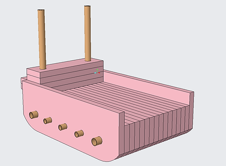
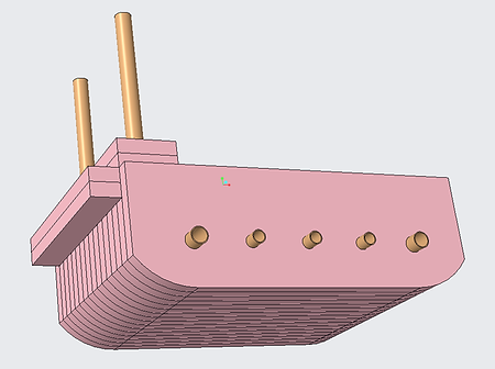
The body of the cart was constructed from sixteen foam sections and five cardboard tubes. Two of the foam sections were two inches taller than the others in order to form a raised edge along the sides of the cart. The body was assembled by placing each foam slab onto the cardboard tubes and taping it to the slab on either side of it.
After all slabs were connected, the entire body was wrapped twice with tape to ensure that none of the layers would get shaken or knocked loose during the competition. Tape was then wrapped around the protruding ends of the cardboard tubes to prevent them from twisting apart and destroying the cart.
Finally, the bottom of the cart was sprayed with adhesive and the laminating film was ironed on to create a smooth contact surface between the cart and the ground.
For the construction of the back support, four foam slabs and two cardboard tubes were used to create a frame on which to hang the canvas backing. This back piece was constructed in the same fashion as the body, with the foam pieces slid onto the tubes and taped to their neighbors. This piece was then attached to the body using many strips of tape in different orientations to ensure that it could not come loose.
The next parts of the cart to be assembled were those constructed from canvas. These included the canvas backing and the harness used to pull the cart. The backing was sewn together with a “hood” on top to hook over the canvas tubes and was then taped along the edges to secure it to the body.
The harness was created using canvas strips and a small metal loop buckle so that it could be easily resized to fit any member of the team. These straps were attached to the cart be threading them through the foremost cardboard tube.
The last component of the design to be constructed was the shield. The shield was constructed from a three foot diameter circle of foam. Straps were then constructed from several layers of tape and were secured by wrapping tape around the front of the shield.
Once the cart was fully constructed, several final tests were performed to ensure that it would hold up to the expected conditions. This was done by having several team members sit on and either block or throw balls to simulate the dodgeball game.


Dodgeball Competition & Race
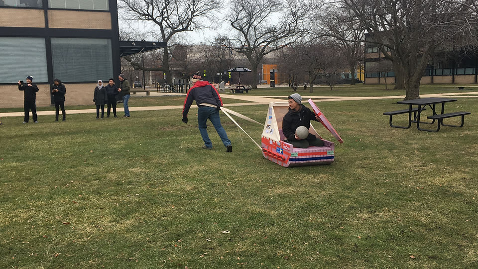
Once the competition day arrived the cart was taken out to the starting location. The cart was neither the heaviest nor the lightest in the Friday lab section. Due to the heat from previous days the snow was melted and we were left with a moist surface to drag the cart along which lead to the driver of the cart tiring quickly compared to other teams.
During the dodgeball competition the cart was able to be maneuvered easily and take sharp turns as long as the driver was able exert enough energy. The rider was also safe from any balls and was not hit while using the shield. The rider was also able to move around in the cart without worrying about damaging it to readjust to throw a ball or to grab a ball off the ground.
During the race, using our lightest rider and strongest puller, we were able to finish middle of the pack. If there was snow on the ground the speed and ease of pulling would have been greatly improved.
After the events events of the competition we wished to test our design to the maximum of its limits so all group members stood on top of the sled
The cart was able to withstand the weight without suffering damage. We also dragged the cart across pavement after the competition to a team members car for storage and checked the plastic layer for damage
The sled was able to surpass our expectations and resulted in a much more durable design than anticipated
From the performance of the competition it can be surmised that the cart could have been much lighter if some of the material were to be removed from the sled itself. As well as the size of the sled could have been cut down as it resulted in a very roomy design for the rider


Competition Day Photos & Videos


